Over a year ago I posted about the work-in-progress of the Space Station Activity Board, with hopes of soon completing the wiring of the board. Moving houses and other projects pushed the Space Station further and further back, and then the dread of a million tiny soldering connections kept me from making any serious progress on it. In the spring of this year, I finally powered through and have a fully functional space station for my toddler.
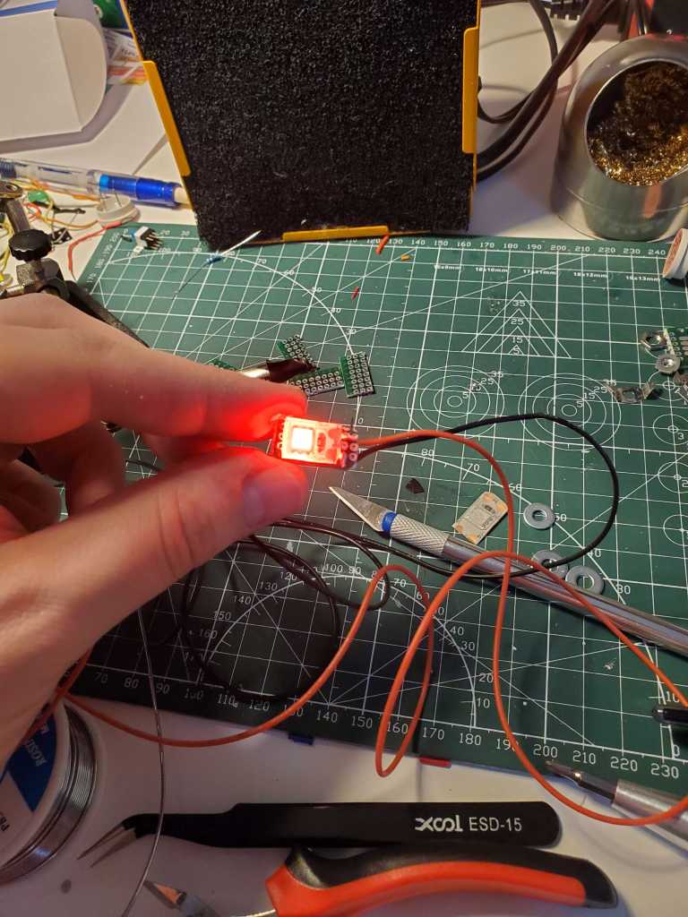
The first step in wiring the whole thing was to make the large leds easier to integrate into the whole thing. The large red leds were 12 V instrument lights primarily for cars, and I wanted to make the powering simple with being able to power the entire thing off of the Arduino Mega that was going to control it. To accomplish this, I removed the original LEDs from the housing and replaced them with my own red LEDs cut from a long LED rope (for the IKEA kitchen upgrade that hopefully I’ll write up soon).

I cut a small piece of prototype board to fit the housing, cut a piece of the red LED off of the strip, tinned it, and soldered it to the board with two leads. The LED strip that I used had built in resistors in each segment, so I didn’t need to worry about anything else.


Once all of the lights had been rewired, I had assembled all of the components for the spacestation: large LEDs, pushbutton switches, toggle switches, rotary knobs, joystick, 16-key keypad, and 7-segment displays. Now all that was left was the large task of wiring them all together.

I began with the most difficult part – soldering the 8 2-digit 7 segment display. In hindsight, I wish I would have just bought segments that had a little bit more of the connections done for me, but this was some good small soldering practice. Each of the 2-digit segments have 10 outputs: 7 for the digits, 1 for the decimal point, and 1 for each digit display. These 7 segments are common cathode displays: each of the 8 segments(7 segments + 1 decimal point) are connected to the positive and each of the digit outputs is connected to the ground.

Overall, the entire 7-segment assembly will take 24 inputs/outputs on the Arduino, since inputs A-G+DP will all be chained together respectively, and each digit output will have its own pin on the Arduino. When more than one 7-segment display is powered by the same outputs, each digit is displayed sequentially, but the Arduino will do so quickly enough that they will all appear to be displaying simultaneously.
My first attempt to chain the segment inputs together was a solder glob mess, mainly because I was using too large of gauge wire that did not allow me to put more than one wire in the breadboard hole.

Once I switched to a smaller gauge of wire that allowed me to put multiple leads into one breadboard hole, the process became a lot easier. Two of the wires were twisted together, tinned, and then pressed into the heated up solder pin of the display. Once they were all wired together, I plugged them into the Arduino for a test run. A few minor breaks or mistakes on the soldering were easily found and fixed.

Unfortunately, after fulling checking and double checking the connection, one half of one of the segments seemed to be permanently destroyed, probably by getting it too hot with the soldering iron.
Once the seven segments were soldered, it was time to solder the rest of the connections. Several breadboards were cut to create common points for common grounds and +5V. The other wiring was fairly straightforward, each other LED or switch is connected to a common +5V or ground and connected to a pin on the Arduino on the other. Nylon spacer stands were glued to the space station and the Arduino screwed into them. I finally got myself a ratcheting crimping tool to turn the wire ends into jumper pins that can easily plug into the Arduino. After a couple tries to get the hang of it, the ends of all of my wires were crimped to jumper pins and connected to the Arduino.

Two options for powering the Arduino were added: a rechargeable battery and a USB port on the outside of the box. Which of the power sources is used is controlled by the three switches near the joystick.
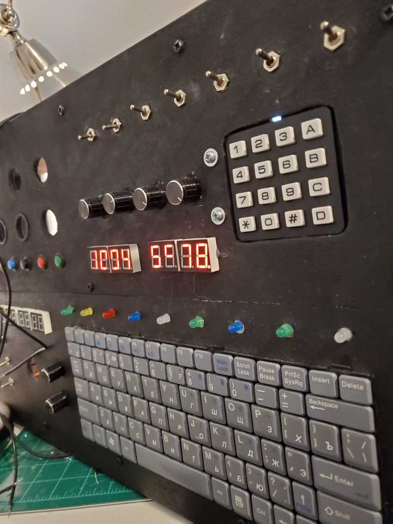
With all of the connections made, the last step was programming the Arduino! The joystick and keyboard were not able to be programmed, I ran out of inputs on the Arduino. The 7 segment displays above the joystick display a heading: two degree measurements, 0 – 360, which are controlled by the two rotary dials by the joystick. The large red LEDs are controlled by the pushbuttons beneath them and the small LEDs are controlled by the toggle switch at the top of the station. Each switch is set to toggle 2-4 of the LEDs, while the states of the LEDs when the board is turned on are randomly set. The keypad controls the output of the left 4 digits on the top of the board, while the right two are a counter that counts up continuously. One of the other 4 rotary dials controls the speed of the counter, while another controls the brightness of the LEDs.


While it took way longer than originally thought (somewhat because I moved twice during the build), I was very happy with the final result. My toddler loves donning her space helmet and pretending to fly off into space. The randomization of the lights is very fun, and the interactivity making the numbers on the 7 segments gives a little depth to the activity.
This was by far the largest electronics project I have completed to date, and even though I was making it up as I went, I really learned quite a bit about planning and executing a project of this scope. If I were to make another one, I would definitely aim to make it more modular – perhaps putting easily removable panels on the front to make the soldering and connecting of the components easier. The space station was created with a 2 year old in mind, now that she is almost 4, I would want to add more interactivity and perhaps sounds. All in all, it was a wonderful learning project.
