One of my favorite stores recently is the University of Minnesota ReUse store – where all of the old, surplus university material is sent to be sold off to the public after its usefulness in the university has come to an end. There is a ton of old and new technology, furniture, and office equipment for sale and I always come away with something awesome for a new project. Recently I came across a pair of old ammeters for a few bucks each.
Loving the look of old, analog dials, I had seen some posts where people have turned them into internet speed monitors. With a handful of Raspberry Pi picos, I decided to try this out for myself.
Hooking up the Dial
First problem was to get the Pico to output to the dial. Connecting is simple – there’s only two terminals! Connect one to the ground pin of the Pico and one of the GPIO pins to the other terminal. Any of the GPIO pins can be used because they are all capable of pulse-width modulation (PWM). If you are using multiple PWM pins with the Pico you do need to take care to make sure they don’t overlap – all the GPIO pins share 16 PWM channels. I’m only using one here, so there’s no problem, I chose GPIO 17. The Pico cannot output a real analog signal, but using PWM at an appropriate frequency I’ll be able to fool the ammeter to outputting an amperage.
To program the Pico I opted for Micro Python as a quick and easy way to get this program up and running. MicroPython is incredibly easy to get up and running on the Pico, just drag and drop the .uf2 file into the memory accessed with the Boot Sel button. The install instructions are found here. To control the dial, I’ll use the PWM module.
I had to do some trial and error to figure out what frequency and duty cycles to set the PWM at to get the dial to respond – frequency being how fast of a digital signal to send to the device and duty cycle being the percentage of the cycle to output high (out of a possible 65535). With this ammeter, a frequency of 1000 Hz worked well to display values. Initially, a duty cycle value of 9300 gave the dial a max value, so I programmed the dial to accept values from 0 to 9300. However, it was not that easy. As I worked on the program and design over several days, the duty cycle values began to vary wildly with the value they printed out. I suspect that this is an environmental cause (the temperature in the winter of my workshop varies wildly) or due to the fact that this ammeter is who knows how old and essentially thrown out by a university department.

The quick and simple counteract that I have for this variation is that I have made a standardized program to run before I start up the program to figure out what the max of the dial is and a customizable sensor program that can adjust to that dial value. Now that I have the dial working and outputting values, I needed to send it the internet speed.
Measuring the Internet Speed
The dial was set up to read in a value from the serial connection and then set that value to the duty cycle of the PWM pin. Unfortunately, reading a serial value on the MicroPython Pico is easier said than done, but luckily I found a good implementation on the Raspberry Pi Forums. Next I needed a program to run on the host computer to determine internet speed and send the value to the Pico over the Serial connection. With Python and the speedtest-cli library, this is incredibly easy!
Install the library with pip install speedtest-cli, and use three lines of python:
import speedtest
st = speedtest.Speedtest()
download_speed = st.download()
Speedtest gives the speeds in bits/s, so divide that value by 1048576 to get the speed in Mbits/s. A serial connection is opened with the serial library and the download speed is sent to the Pico. Since my internet service is a little under 1 Gbps, I scale the download speed linearly to fit the min and max of the dial, with 0 Gbps down being 0 on the dial and 1 Gbps down being 1 on the dial. This gives a nice visual of how far away my current speed is from absolute max. To get the dial going, I just need to plug the Pico into a PC and then run my internet Python script in the background.
Building the Shell
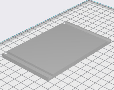
To finish the project off, I needed a nice compact case for the dial and the Pico. The construction of a case was made easy by the dial already having four long machine screws poking out of the back of the machine, ready to bolt a case onto. The key to a successful prototype is small iterations – don’t try to do the entire thing at once, especially since I am trying to fit this case on a device I don’t have the exact measurements for. To start, I measured the distance between the centers of the four screws on the back of the and created a bracket to slip over the four screws.

The first iteration was a failure – the cylinder on the back is too low to fit the rectangle, so an oval hole needed to be added.

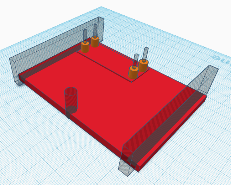
Originally, I had planned that the mounting rectangle would be bolted on, then the back case would slip into a groove on the back of the mounting rectangle. This proved difficult to actually work in my first test print, so I switched to only the back panel clipping on the main panel. So my next iteration fit the side panels on top of the mounting rectangle. The ammeter rests very stably on its base, so I decided to not try to fit a base on the case and only enclose the sides and top to hide the internals.


For the back cover I first printed out a back cover that would slide onto the two sides for easy accessibly to the chip inside it.
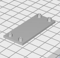
I also test printed the Pico standoff before I integrated it into the full model, to make sure it would work. This testing paid off because my first attempt the standoffs were off by a few millimeters due to misreading the Pico design schematics!
Putting It All Together
Combining the two models together, I have a back case, and now I just have to put the whole thing together. The Pico will be connected to the computer with its USB cable, so it only needs the two leads that go to the ammeter soldered on.

I soldered wires to GPIO 17 and the GND pin and screwed the Pico into the back cover. I only had fairly long M2 screws, so I had to use some nylon nuts to increase the standoff.

It looked all ready to put together, but, alas, I ran into one final design problem! I set the Pico nice and centered, not thinking at all about the length of the USB plug! Even after removing the stiff cable cover it was too long without really ripping it apart.

Back to the drawing board, I offset the Pico standoff so that it would fit. At the same time, I increased the standoff size so that they would accommodate my longer screws.
With my updated model, everything fit perfectly! I ran out of the red PLA though, so I had to use grey.

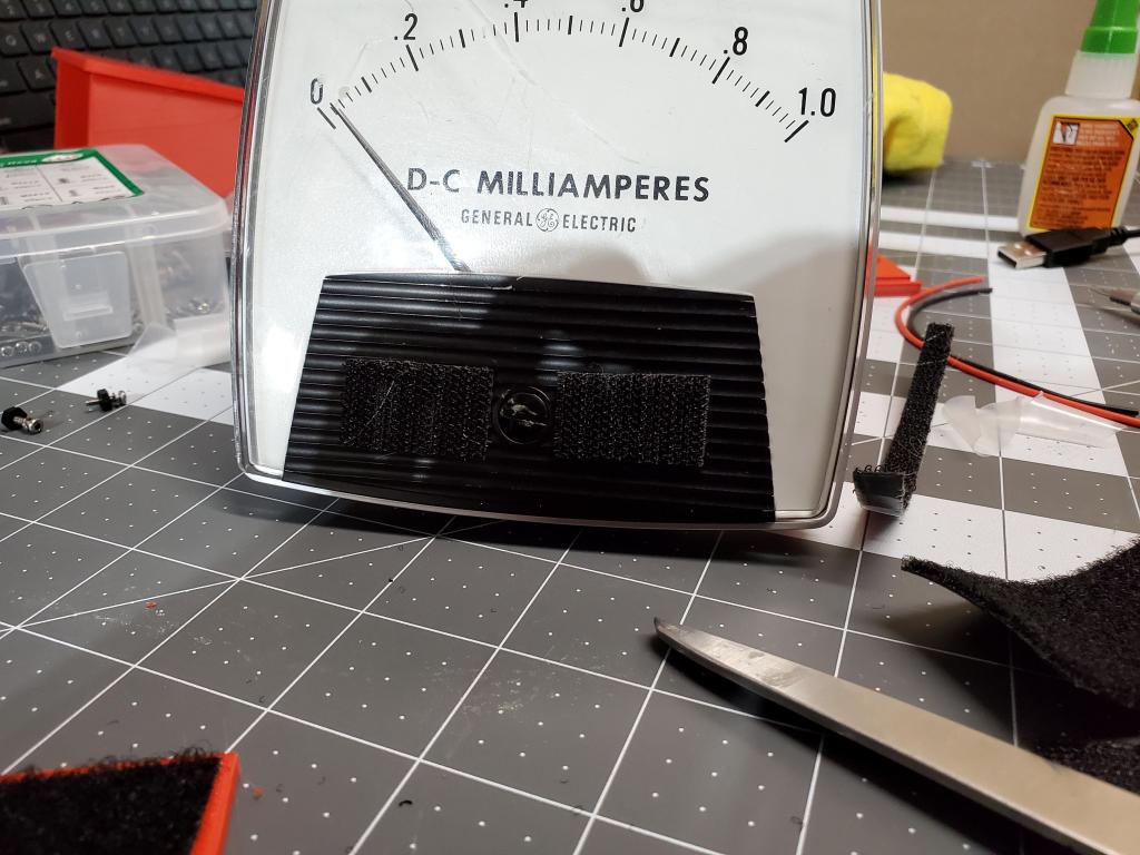
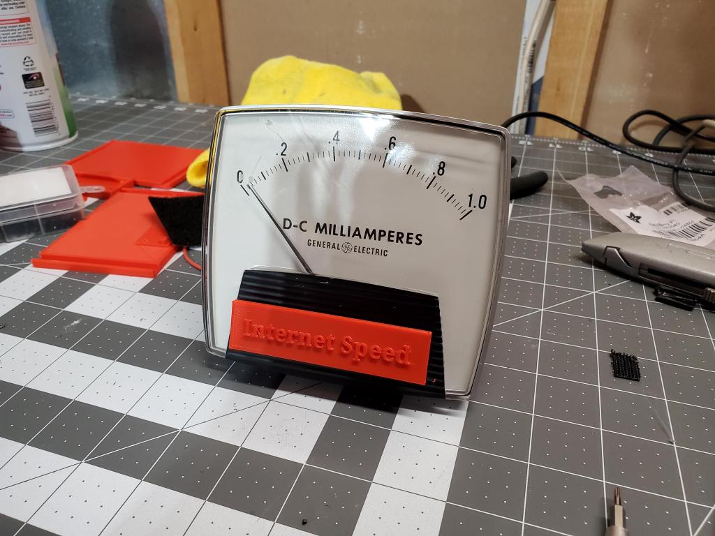
To finish off the dial, I made a little display badge to denote what it is displaying, and attached it with adhesive velcro, in case I want to change up what it is displaying in the future. Changing its output would be incredibly easy since only the program running needs to change what information it sends the Pico on the serial line.
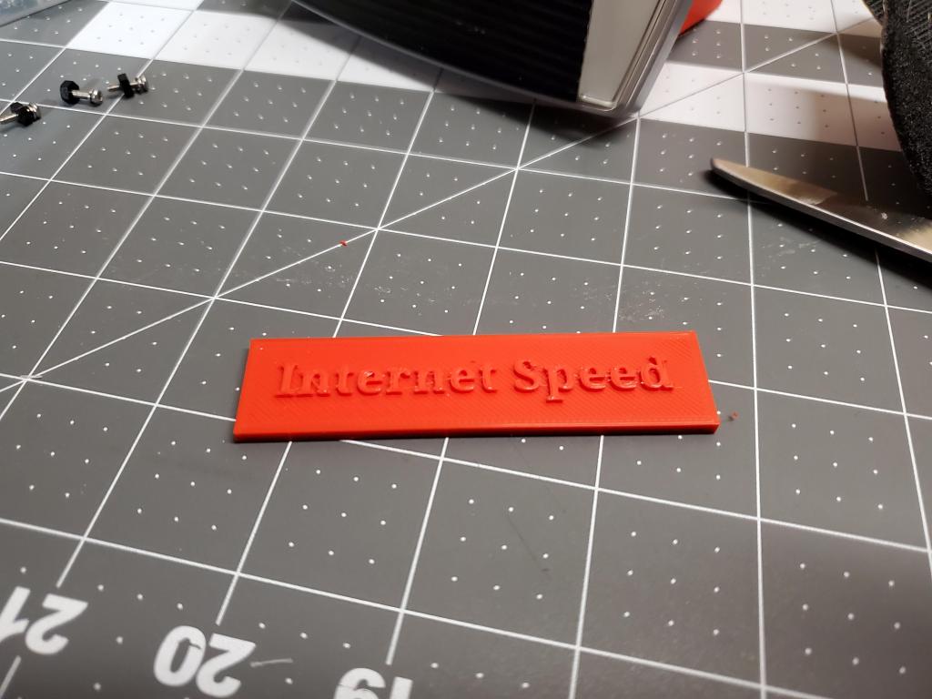

With the badge on and connected to the computer, the dial is complete! Running the python script on its host computer has the dial move to show the current download speed.
This project was a fantastic little build for practicing working with a Pico, which I am going to put into a lot more projects in the future, as well as 3d modeling and printing.
If you are interested in the code I used, you can find it on my Github.
You can find the 3d files that I used on my PrusaPrinters page.
