I have long been fascinated by old electronics and computers, restoring them, and refurbishing them for a new purpose. So I have been kicking around several ideas of taking old, broken electronics that would not be able to be restored in any meaningful way and finding a new functionality for them. So when I found this old Automatic Electric rotary telephone at an antique mall for $30, I knew I had a good candidate for rehab on my hands.

It was certainly beaten up over time and a bit grimy, but the handset and cord seemed in good condition and the rotary dial was functioning perfectly. The switch that receiver sat on was stuck and the landline that was hardwired in was completely in tatters.
Dissecting the Phone:


They don’t make ’em like they used to – all of the components are incredibly easy to disassemble with simple screws and the inside of the phone contained an immaculate wiring and circuit diagram for the inside the phone.

The bulkier internals are easily removed with more screws, leaving plenty of room to add modern electronics. I would have like to keep the original ringer, however I’m planning on using low powered boards to run the phone now, and the ringer is made for high voltage regular phone lines. Once I getting the entire phone functional, I may return to the original ringer and see if I can integrate it; however, I wanted to get the basic phone up and running as soon as possible. The large circuit box under the dial was not going to get any more use, so it was removed as well. It was held in place with a few screws and a thick sticky substance anchoring it to the base.

The only damage so far I’ve inflicted was the bottom right screw attaching the rotary dial – it was so rusted it snapped off when I tried to remove it, leaving half of it firmly implanted in the base. The remaining screws hold it in firmly enough, I think, for functionality.
Functionality: Handset

The handset is connected to the phone with three wires – yellow, green, and red. I soldered on some jumper wires to connect it easier for testing. This was much more difficult than I hoped, as the wires inside were thin and incredibly fragile.
These were easily tested on a breadboard, applying small voltages to one of the wires and grounding the others with LEDs. Observing the outputs from the speaker and mic, I was able to identify the Yellow as the signal for the headphones, read as the signal for the microphone, and the green as the ground.
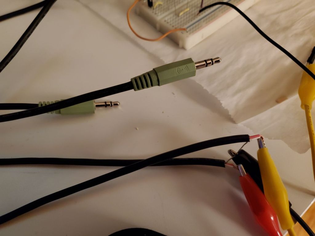
To test the handset, I got an old speaker cable, split it, and stripped the wires. Opening the wires gives three wires each: a left and right audio and a ground. Since this phone is mono, I wired the handset speakers to both of the headphone audio wires, the headset microphone to the microphone plug wires, and the both grounds were connected to the phone ground. With this simple connection, the handset is easily plugged into my main PC and used in place of my normal headphones and mic! The handset works excellently as a headphone/microphone combo, with an audio richness expected from a decades old analog phone.
Functionality: Handset Switch


The switch for the handset is controlled by a large metal bar attached to a spring, which pushes the bars contacts into the switching mechanism (shown above). When the phone is assembled, the two posts the handset rest on press down onto the switch, breaking the switch open. There are five wires coming out of switch – red, green, yellow, black, and white. Following the wires overhead, the switch connects the pair of green and yellow to the pair of black and white.

Since the switch is only going to be used as an on/off control switch, I twisted the pairs together and spliced them onto additional wires. These can easily be attached to the GPIO on the Raspberry pi to control functions of the phone.
This has been a great project so far to combine breaking down old electronics, electronics circuitry/breadboarding, and software development. Next up date I’ll break down the next stages – getting the rotary dial set up and connecting it all together with the Arduino and the Raspberry Pi.
